

The mythical Ibanez Tube Screamer is not free of issues ! Let's talk about why I dislike its sound so much.
shopping_cart
0
Latest posts
-
 Why does the Tube Screamer sound bad ?Read more
 -
 Master fuzz clean-up like a pro !Read more
Let's talk about volume clean-up, vintage fuzzes and buffer pedals, and how everything interacts together.
-
 Circuit Analysis : Electro Harmonix LPB1Read more
Let's dive deep into electronics and explore the Electro Harmonix LPB1 and Screaming bird at once !
-
 Master the art of reampingRead more
Let's talk about how to use a DI box and a reamp box and what they are doing under the hood.
-
 How to record an electric guitar : all about microphonesRead more
All you ever wanted to know about recording your electric guitar amplifier with microphones, but were afraid to ask !
-
 Guitar preamps: are they a scam?Read more
Understand what really is a guitar preamp pedal, its difference with a studio preamp and an overdrive pedal, and how...
-
 The art of stacking effects pedalsRead more
Discover how to master pedal stacking with overdrives, saturations, compressors, and time-based effects. Learn the...
-
 The ultimate power supply guideRead more
Let's explore what make a good power supply, how to choose one and how to read their labels to prevent frying up your...
-
 Flanger is the BEST modulation pedalRead more
Hot take : flanger is definitely the best modulation effect ever invented. I can have it replace a phaser, a chorus...
-
 The ultimate guide about modulation effectsRead more
Modulation effect pedals form a distinct category of guitar pedals. What are the differences between a chorus, a...
Blog categories
Search in blog
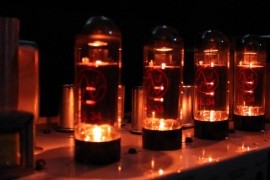
The vacuum tube explained
Today, we’re diving into physics, vacuum tubes, and electronics. Don’t run away just yet—I’m going to simplify everything! You don’t need any prior knowledge, and this lesson is free, so make the most of it.
Vacuum tubes are a technology that peaked in the 1970s and largely disappeared a decade later. Yet, they’re still used in military equipment and—more importantly—in our guitar amplifiers! That’s because tubes, when pushed into saturation, create a unique sound that has literally defined the tone of the electric guitar. Amplifiers come with various types of tubes, each with specific characteristics. But do you really know how they work? Let’s explore the history of vacuum tubes before diving into the most common audio tube models in a future article.
1. A beautiful invention : the vacuum diode
Invented in 1904 by John Ambrose Fleming, the very first vacuum tube, originally called an audion, worked as a diode. A diode allows current to flow in only one direction. Each of its poles is called an electrode, so a diode has two poles (di-odes).
A vacuum diode consists of two conductive elements inside a sealed, airless glass envelope—hence the name. The tube contains almost no gas. Its operation is based on thermionic emission, a simple concept: one of the conductors, called the cathode, is heated to excite its electrons. When heated, these electrons move much faster than in a cold metal. Another conductor inside the tube, called the anode, attracts these excited electrons when it has a sufficiently positive potential.
Since electrons carry a negative charge, they are naturally drawn to a positive potential, moving from the cathode to the anode across the vacuum. However, if the anode’s potential is more negative than the cathode’s, the electrons stay still—no current flows. This is the principle of the diode: when the anode’s voltage is positive relative to the cathode, current flows; when it’s negative, current doesn’t flow. Current, therefore, travels in only one direction.
The cathode is heated to achieve this effect—it’s not just placed near a radiator! Initially, the cathode was heated directly by running an electric current through it (thanks to the Joule effect). However, this direct heating method introduced nonlinearities and required expensive batteries or transformers. Later, indirectly heated tubes were developed, using a dedicated filament placed near the cathode. This method created the same heating effect with fewer drawbacks.
When you see a tube glowing slightly, it’s the heating system emitting a dim light—much like an old-school filament bulb but without lighting up an entire room. And remember: no current flows in a diode until the cathode is hot. That’s the warm-up period we often hear about with tube amplifiers.
2. World’s first amplifier : the triode
If you followed the first section, well done! The next part is simpler.
In 1906, Lee De Forest added a third conductor to the cathode and anode, known as the grid, creating the first triode. This grid acts like the valve on a faucet. Positioned closer to the cathode than the anode, it has greater influence on the electrons passing through the triode.
When the cathode is hot and the anode has sufficient voltage, electrons are drawn to the anode but now encounter the grid along their way. The more negative the grid is, the more it repels the electrons, reducing the current—like closing a faucet. By applying an electrical signal (such as your guitar signal) to the grid, we control the flow of electrons in the tube and, thus, the electrical current.
This principle is what allows the triode to amplify the guitar signal, which is precisely how most low-power tubes work in guitar amplifiers.
3. The loudness war : the tetrode and pentode
Diodes and triodes open a world of possibilities, especially for things like radio receivers. But there’s a catch, as they don’t provide much power and can’t really amplify higher frequencies like radio signals.
Adding a fourth electrode—called the screen grid—near the anode allows the tube to amplify much higher frequencies and deliver more power. This four-electrode design is called a tetrode, with the iconic 6L6 being a common example used in Fender amplifiers.
Faster operation is great, but it has a side effect: electrons, moving at high speed, crash into the anode, knocking loose anode’s own electrons. These secondary electrons are then attracted to the screen grid, reducing its efficiency.
To solve this, a fifth electrode—called the suppressor grid—is introduced to “capture” these stray electrons. This five-electrode tube, called a pentode, comes in several forms, such as the smaller EL84 and the larger EL34, both popular in Marshall amplifiers. Smaller pentodes, like the EF86, amplify low-power signals and were famously used in vintage Vox amplifiers.
4. Pushing the Limits
From this point, engineers of the time went wild, creating tubes with ever-more grids (hexodes, heptodes) for specialized radio mixing and modulation tasks. They developed combination tubes (e.g. triode-pentode hybrids) to cut costs and improve versatility. Massive, powerful tubes capable of delivering megawatts of radio waves powered antennas worldwide.
The 1960s and 1970s were the golden age of tube manufacturing and radio communication. In France, this was the heyday of AM radios. But this technology quickly faded with the invention of the transistor, which drastically reduced the size and cost of amplification systems from the mid-1970s onward.
Today, vacuum tubes are only used in a few niche scientific applications, radar systems, military equipment, and, of course, audio devices. Here, they play a key role in creating the unique sound we love from our amplifiers, which you can read about in this article.
Related posts
-
 Audio vacuum tubes for dummies
What are the most used vacuum tubes in audio and guitar amplifiers ? What does 12AX7, GZ34 or EL84 do to the sound ?...Read more
Audio vacuum tubes for dummies
What are the most used vacuum tubes in audio and guitar amplifiers ? What does 12AX7, GZ34 or EL84 do to the sound ?...Read more -
 True Bypass vs Buffer Bypass : understanding your guitar pedal's signal path
Learn the difference between true bypass and buffer bypass to optimize your guitar signal. Avoid tone loss and...Read more
True Bypass vs Buffer Bypass : understanding your guitar pedal's signal path
Learn the difference between true bypass and buffer bypass to optimize your guitar signal. Avoid tone loss and...Read more -
 Choosing guitar cables: enhance your sound quality
Learn how guitar cables influence your tone. From capacitance to shielding and tips to maintain signal clarity,...Read more
Choosing guitar cables: enhance your sound quality
Learn how guitar cables influence your tone. From capacitance to shielding and tips to maintain signal clarity,...Read more -
The ultimate power supply guide
Let's explore what make a good power supply, how to choose one and how to read their labels to prevent frying up your...Read more
-
How to record an electric guitar : all about microphones
All you ever wanted to know about recording your electric guitar amplifier with microphones, but were afraid to ask !Read more
Leave a comment